Robot for Pallet Transportation - ATI Motors
May 2025 - August 2025
Goal: To build a prototype of an intelligent fork for pallet transportation to be used in warehouses and factories.
I undertook this project in the summer of 2025, during my internship at ATI Motors. “Skateboard” was the nickname given to the project.
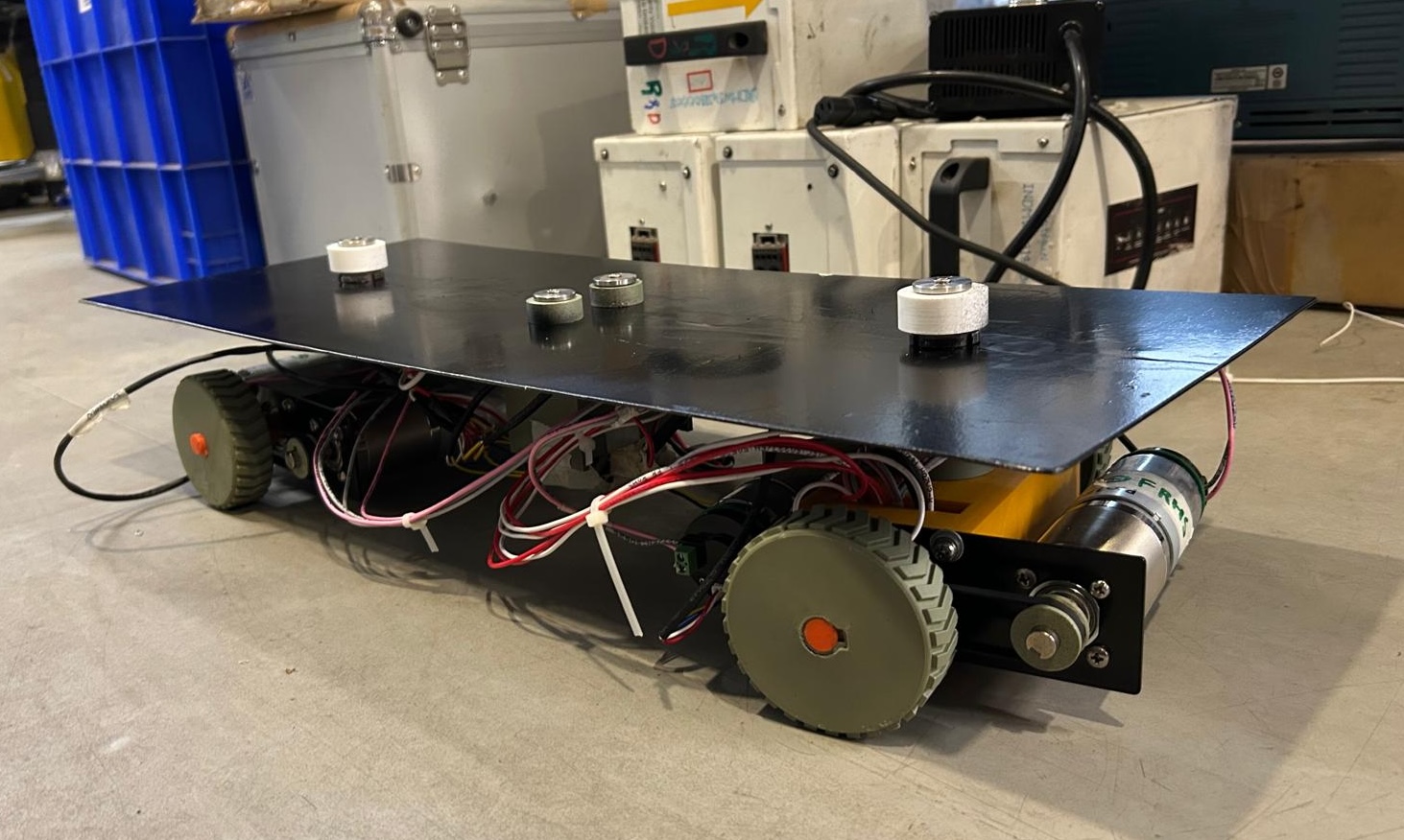
The skateboard’s key advantage over pallet movers and similar machines is its ability to move omnidirectionally and perform zero-radius turns. This increases positional accuracy and could potentially save time and space. It also uses an electronic differential rather than a mechanical one, which is more compact and precise.
Design Process
For this project, I used Onshape for CAD work, SimScale for FEA analysis, and the Arduino IDE for hardware tasks. Most parts were either 3D-printed, laser-cut, or CNC machined.
Before I began, some components such as the motors, encoders, pulleys, and microcontrollers had already been selected by the company. To fit the given constraints, I designed my own GT2 pulleys and other parts for the electronic differential unit.
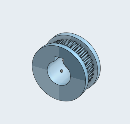
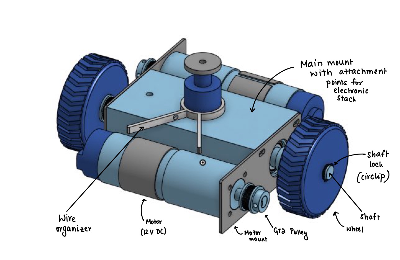
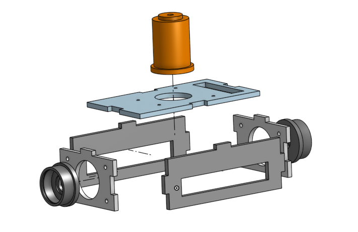
The above image shows the CAD assembly of the drive unit. The motor mount was designed as a sheet metal part to be laser cut in IS-2062 E250 (Hot-rolled steel). The rest of the parts were to be 3D printed in PLA, except for the tire treads which were TPU.
Design Justification
- Custom-made GT2 Pulleys - Due to the large diameter of the selected motor’s shaft, I was not able to find existing GT2 pulleys in the market to fit it. Hence, I FDM printed my own to validate the 1:1 pulley ratio and operation of the motors. I also settled on using a shaft key because adding brass inserts in the pulley caused the plastic to deform.
- Laser cut Motor Mount - The motor mount was laser cut because after performing FEA, I noticed that the PLA would deform from the weight of the motor (852 g).
- Cuboidal shape of Main Mount - To fit the Arduino Uno R4 and Motor Driver Shield that were stacked.
- Wire Organizer - To prevent the wires coming out of the differential unit getting tangled since the unit freely rotates.
Through this iterative process, I kept testing and modifiying my designs till the tolerances were tight, and parts moved as expected.
Electronics and Test Bench
The drive units were designed to fit the electronics stacks in the middle.
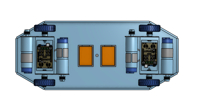
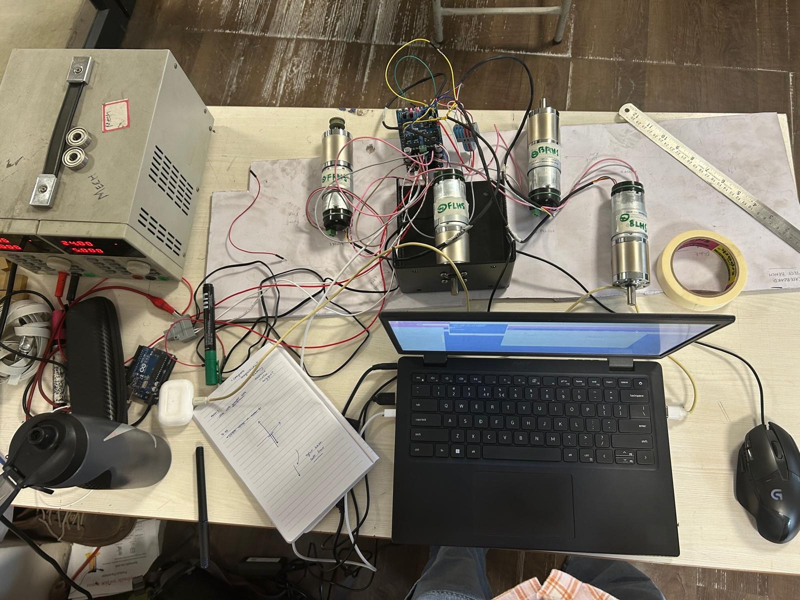
The circuit consisted of a stack of an Arduino and two motor driver shields that powered and controlled the four motors using data from quadrature encoders. I wrote a PID-based program that monitored the ticks and positions of the wheels’ rotations.
My options for different methods for communicating with the microcontroller system were:
- Blynk (an IoT platform)
- Pros: Easier set-up and debugging
- Cons: Lesser customaization and was facing issues of high latency
- MQTT
- Pros: Low latency and High Customization
- Cons: Requires an external broker
- Wi-Fi communication over a Flask server
- Pros: High Customization and allows for the creation of a custom dashboard
- Cons: Medium Latency
Ultimately I chose the third option and ran a web server on my laptop to control the Arduino with an ESP32. To validate my code and setup, I created a test bench with the motors and all electronic components.
Issues Faced with Electronics
- Large time delay between data fetching and execution - After testing the Flask server to find the problem area, I found that the Arduino was struggling to parse the data. I modified the code so that data was sent as a string (a small package of files) rather than a JSON>
- Damage of an Arduino - During testing, I fried one of the Arduinos. It would take a while to receive another, so I modified the code such that both drive units recieve instructions from one Arduino, and both Motor Driver Shields are stacked on top of each other.
Assembly
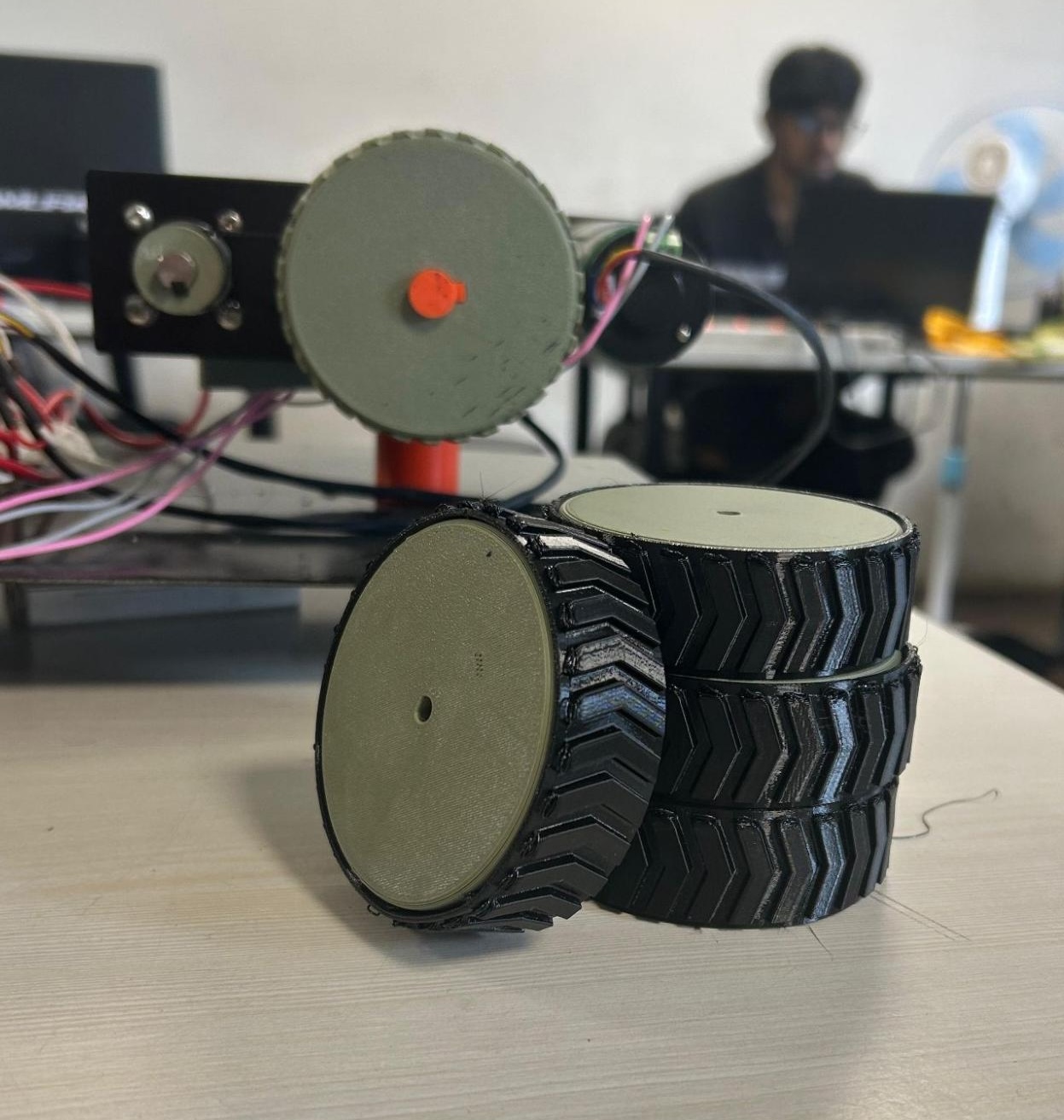
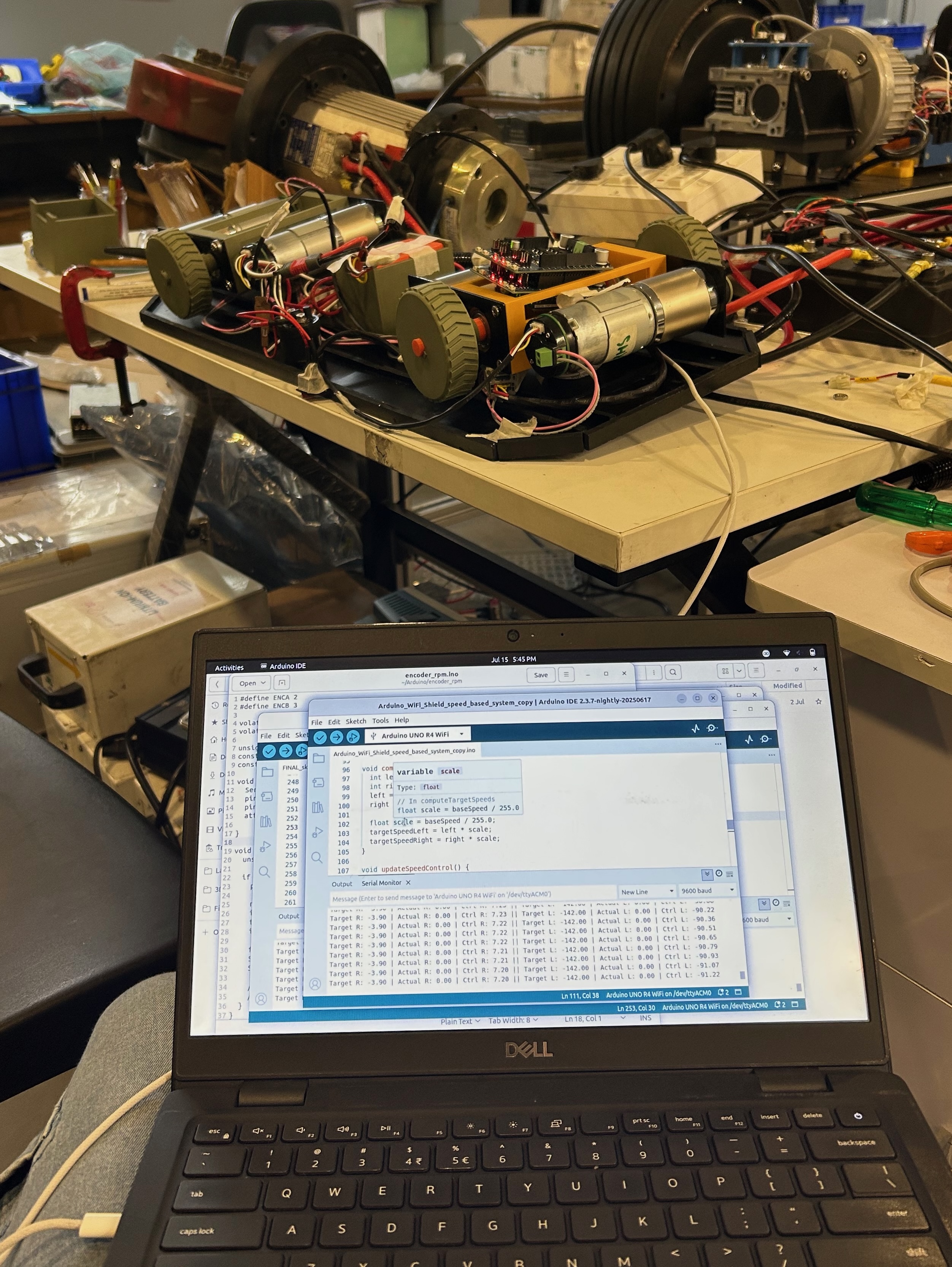
I then moved on to assembling all the parts, which had been manufactured by then. During this process, I realized that the foamboard was too weak to hold the weight of the motors, so I cut and drilled holes into a piece of scrap metal instead.
Issues Faced during Assembly
- Breakage of the shaft - The shaft would keep snapping, so I reprinted with 100% infill.
- Wires prevented the free rotation of the drive unit - Since I was using one Arduino, there were a lot of cables running between both differential units preventing 360 degree rotation of each unit.
At the end, I was able to run the prototype on the ground and test my code and other ideas.
With the design approved by the company CEO, I moved on to getting all parts manufactured in metal. This meant modifying some of the designs for better manufacturability.
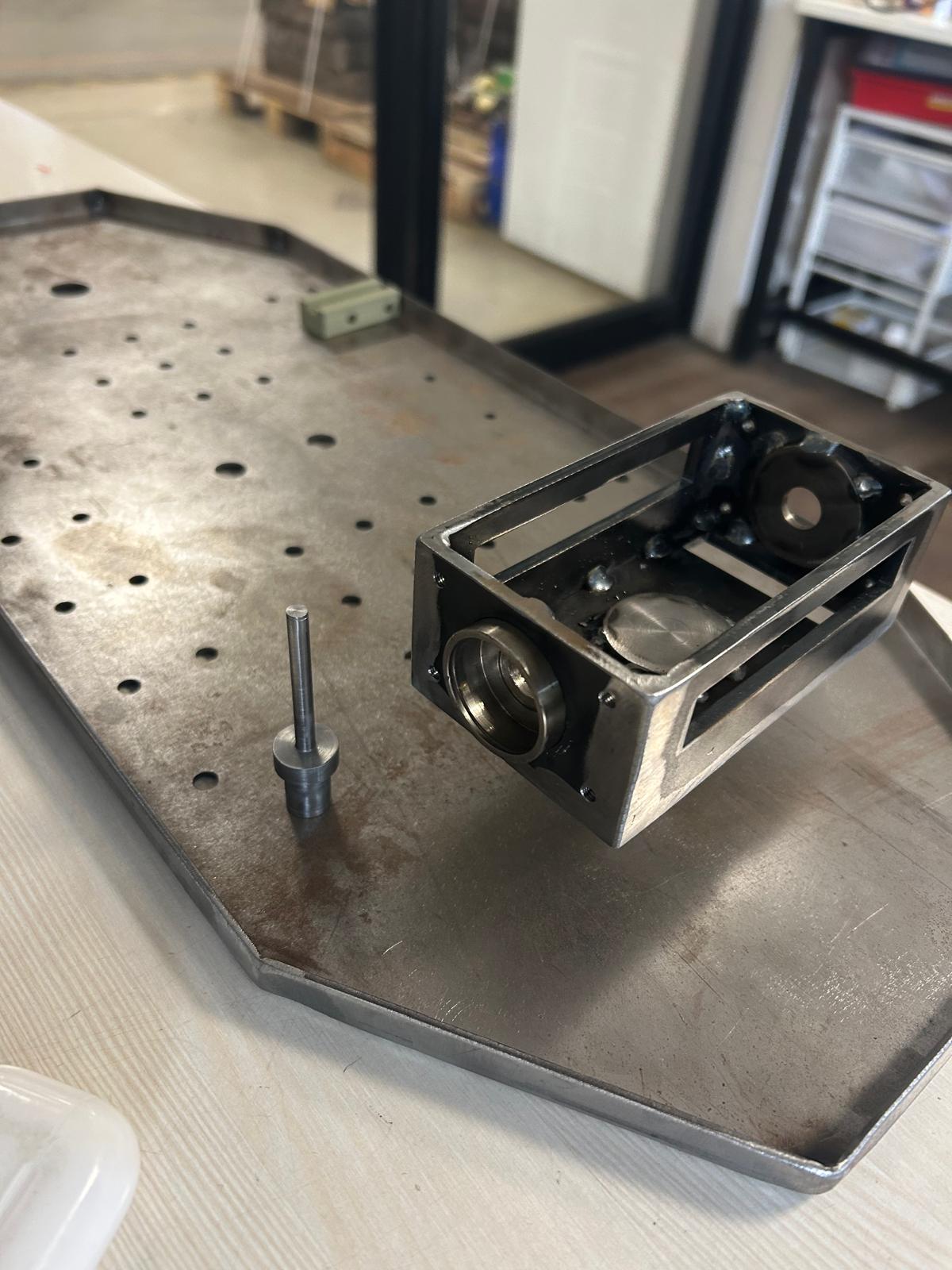
Overall, I was able to successfully validate the idea with a working prototype. Although I wasn’t able to fully build and test the metal version within the internship, the company plans to continue developing my work into an actual product.
I truly enjoyed the learning process, and it was gratifying to see the final product come to life. I look forward to taking on more challenging and interesting projects like this in the future!